|
Use
E-XD++ Enterprise Edition visualization, rapid construction of
specialized electronic circuit design and simulation platform!
-
100% VC + + MFC development, more than 500 thousands lines of
effective VC + + source code, the official
version of all the offers without any reservations!
 Download this
solution
Integrated
electronic circuit design and simulation
solutions in E-XD++
visualization component library is an important
solution,
E-XD++
Visualization Graphics is a 100% Visual C++ / MFC
based Vector Editor, it ships with complete source
codes, it contains the most popular electronic
circuit design, editing capabilities features.
From the first version of E-XD++, it already has the
full features on circuit network diagram Design, the
current version of E-XD++ has performed its
functions to extreme, basically, if you want to
build any very professional Multisim NI
Schematic like circuit design and simulation or Other
real time graphics based applications, E-XD++
will be the best choice. It has almost all the
features of a very professional circuit design
software. It supports SVG Importing and Exporting.
DXF Importing and Exporting, XML Loading and Sving,
many kinds of electronic circuit symbols. The VBScript &
JavaScript is used for action controlling of any
shapes on the canvas. It will be the best
choice for building your own "Full Customized"
Industry software, you do not event need to write
one line of code, a very professional and complete
functional Multisim like application is created, it will saves
you at least 80% of building time and a lot of
money.
Interface <MultisimDemo>
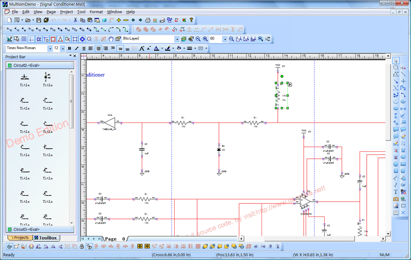
Product basic functions:
1 A new
project:
Invoke
the following dialog box, create a new
MultisimDemo projects:
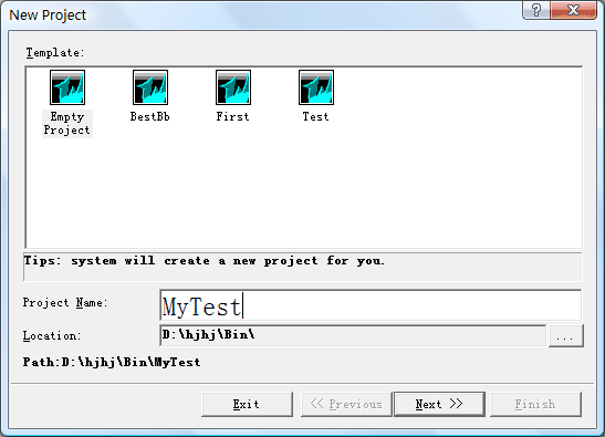
Subsequently,
the project manager will be automatically selected to create a
working directory under the directory, the directory name is the
project name entered by the user. This new
generation of projects has included a lot of information inside,
including the default user, and the default configuration
information, the user can modify the application process.
Note:
The user-generated new projects will be added to the project list.
2
Open an existing project
Select
the menu "File / Open Project" command, the pop-up "Browse for
folder" dialog box, select the path where the existing projects.
Click
"OK" button to open the project file.
If
you add the project name and the current project list the project
with the same name already exists, then the path where if two
projects are the same, the list will work covered by existing
projects; if the two projects the path of the different projects
will add a list of the same name works.
You
can also open the file menu, select the mcp
file format directly to open the project file.
3
Save an existing project
Select
the menu "File / Save Project" command, the system will
automatically save the current project file and save all the
modified documentation.
4
off an existing project
Select
the menu "File / Close project" command, the system will
automatically save the current open documents is good, and then
close the project file.
5
most recent list of project files
The
system automatically works to recently opened files are listed in
the bottom of the menu, by clicking on the name of any one project
open the project file sub-menu.
6
window manager
In
the Window menu in a series of sub-menu on the canvas so that you
can easily switch between any sub-menu, and other operations.
7
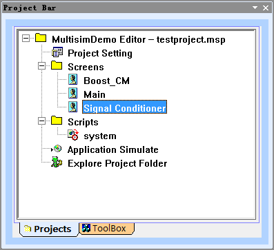
Project Tree
Tool
box on the left there will be a project tree, the tree is listed in
the project all the images in the current project files and
script files resources.
Click the right mouse button you can add new pictures
or add new script file.
The
newly added script files will be automatically placed in the
specified folder to save.
Double-click
the picture or the tree in the script file you can open the file for
editing.
Below:
8 Add
new picture
Tool
box on the left there will be a project tree, the tree control in
the right-click option to add sub-menu screen (you can also directly
select the main menu "Project | Insert a new image") to add new
pictures.
Added
new screen will automatically use the project default settings on
this screen.
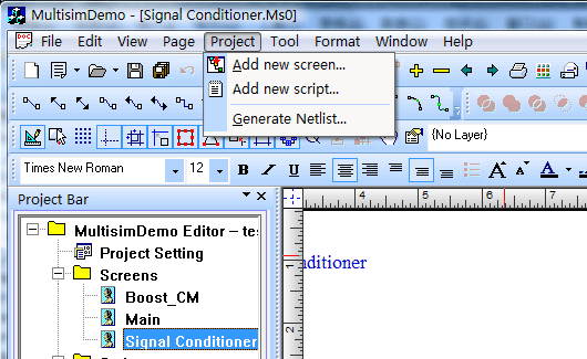
If
you want to modify the properties of the screen, use the right mouse
button menu or the main menu to carry out.
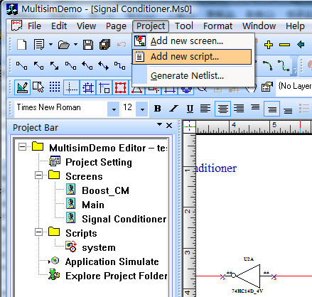
9 Add a new
script
Tool
box on the left there will be a project tree, the tree control in
the right-click the option "Add a new script" sub-menu (you can also
directly select the main menu "Project | Insert a new script") to
add new The script file.
Added
new script file will automatically use the project-related settings.
Project
tree by double-clicking the file icon to edit the script file.
If
you need to call the system editing functions, you can double-click
on the right list of functions where the function icons to increase.
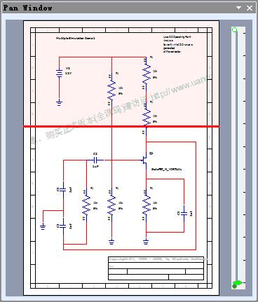
10 bird's eye
view window
Aerial
view of the window system functions can be used for global control.
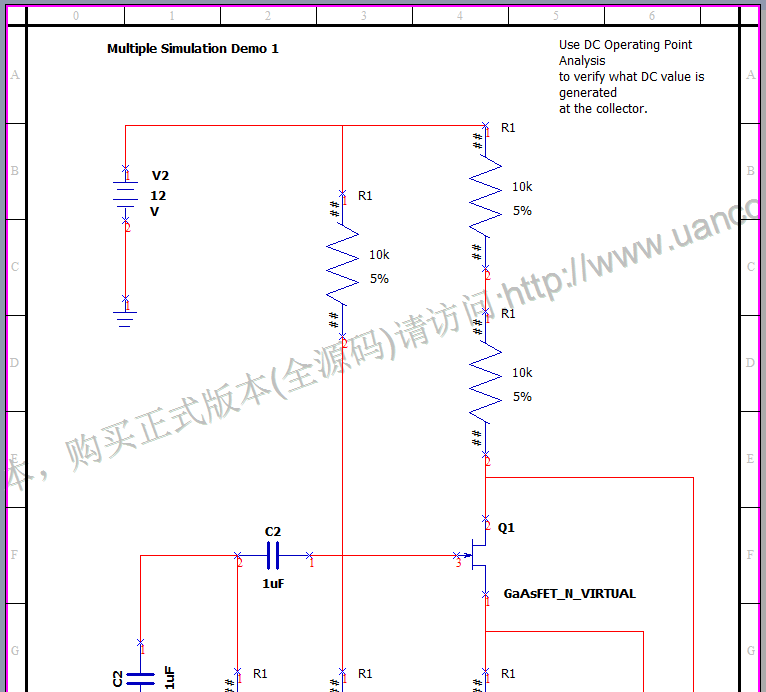
11
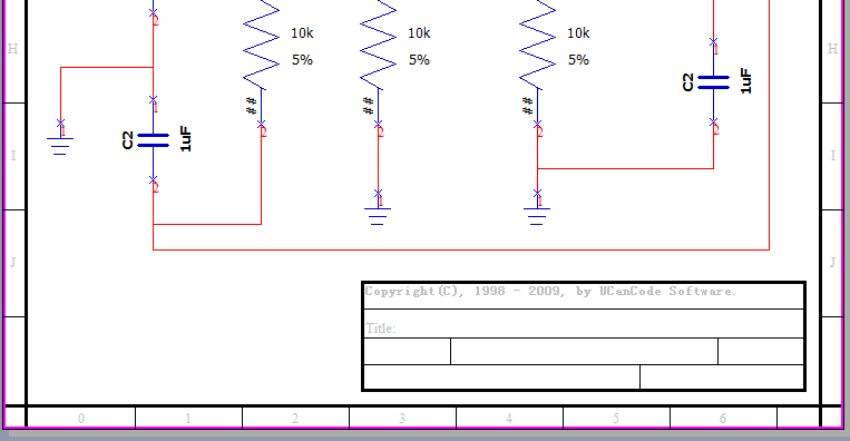
picture frame features
Special
canvas to draw
the border, as shown below.
12 Script
Feature
System
supports the footnote function of the canvas can be used to design
and edit a footnote:
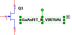
13. components for editing and moving text labels
System
of composite circuit elements that can be marked in the label
directly edit the text and location of mobile, as follows:
1), double-click the text to edit.
2),
click twice on the text label to select it, and move the location.
Below:
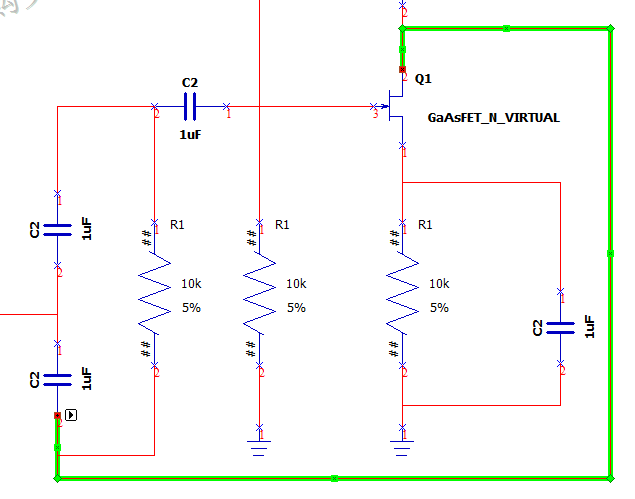
14. created between the components and connections
between components
Use
the mouse to click on any one component stops, you can create a
connection from that point line, and the connection line can be
broken several times, and can adjust its position, as shown below:
15, components and the logical
relationship between the components:
All
the canvas has a beginning and end connector two endpoints, and all
the cable has a clear logical relationship, such as the starting
point from which to connect to any device what position and so on.
16, automatically generated
NetList:
Select
"Project | automatically generated list
of nodes" to automatically generate excel
format netlist file.
17, scroll the mouse center button
to automatically scale the canvas:
In
the center of the canvas scroll mouse wheel can automatically zoom
in on the canvas.
18, canvas translation:
Select the toolbar canvas shift
button on the canvas to pan.
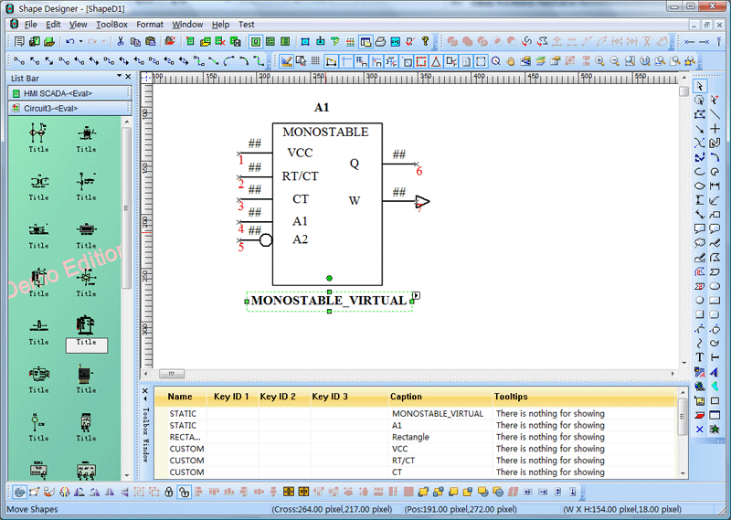
19,
the design of electronic
circuit simulation components:
E-XD++ provides a
professional designer ShapeDesigner
components to help you quickly design all kinds of simulation
components, all components were all vector graphics.
Below:
20,
System Preferences circuit elements:
System provides a large number of components,
all of these components as vector graphics.
Below is a diagram:
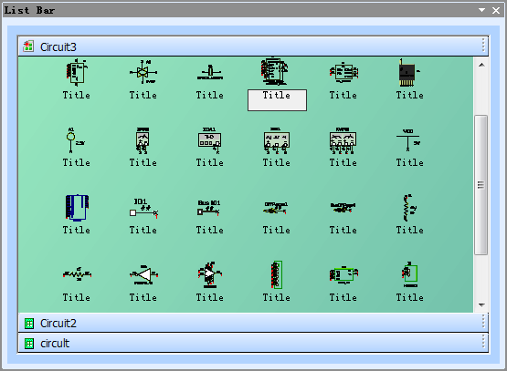
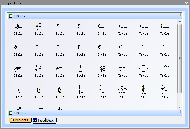
21, provided
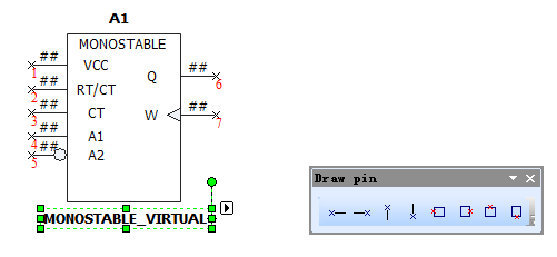
for the circuit design of the pin docking points:
Circuit
elements pin design is very complex, a variety of shapes to choose
from, and be exposed to the composite components for a variety of
external wiring, this end, we designed a pin for circuit stops, the
following toolbar:
21, Other
E-XD++
the official version of the solution provides more than 500 thousands lines of VC + + source code, you will be
developing similar applications save a lot of development time.
Up
to hundreds of its features is difficult to fully listed in an
article.
More
than 500 thousands lines "all
carefully designed and rigorously tested"
C/C++/.NET source codes, all complete source
codes is shipped without
any reservations!
Provide
more than 400 C + + extension class, more than 500 thousands lines of effective VC++ / MFC source code, more than 70
ready to use solution's source code, complete and
detailed online help system and user documentation,
supporting development tools designed!
Powerful,
flexible and easy to use graphical visualization of
source code libraries.
Powerful
and flexible components to create a variety of charts to meet
your needs.
Product
design specifications, it is easy to use, in just a
few days can be designed according to your needs
products.
We
provide complete support for products, download the
trial.
Feature-rich.
Ultra-versatile,
such as automatic layout, multi-level collapsible
subgraph, cell connection point, XML, DXF, SHP, SVG,
etc., can help you quickly create complex and
flexible chart.
Supports
a number of events: such as click, double click,
hover, select, rubber band select, copy, delete,
resize and move the support.
Support
the most complex operations: such as drag and drop,
unlimited undo / redo and clipboard operations and
so on.
Save
time and money to obtain reliability.
A
picture is worth a thousand words, E-XD++ offer more
than 500 thousands lines of well-designed and
well-tested C/C + +/.NET source code!
Development
takes years, thousands of customers worldwide
validation, can save you a lot of development time
and money!
Try
it now!
Do
not just listen to us say it a try!
Our
free trial includes all you need to prototype your
application.
Free
technical support.
 Download this
solution

 The official
version of the E-XD++ component library visual
graphics solutions for enterprise version provides
all the source code, click the button below to order
from UCanCode
:

News :
1
UCanCode Advance E-XD++
CAD Drawing and Printing Solution
Source Code Solution for C/C++, .NET V2025 is released!
2
UCanCode Advance E-XD++
HMI & SCADA Source Code Solution for C/C++, .NET V2025 is released!
3
UCanCode
Advance E-XD++ GIS SVG Drawing and Printing Solution
Source Code Solution for C/C++, .NET V2025 is released!
Contact UCanCode Software
To buy the source code or learn more about with:
|


