|
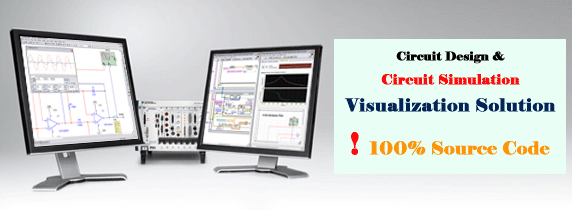
Circuit Design and interactive simulation, Animation and Circuit analysis,
Circuit layout visualization C/C++ and .NET Source Code solution

Product Tour
E-XD++ and UCCDraw product walkthrough
 Screenshots
Applications built on E-XD++
ToolKit
 Product feature comparison
 Download Prebuild Evaluation Kit of Solution
Multisim Video
Build your own Multisim like circuit design
and simulation application!
Diagrams are a
natural and intuitive way of expressing relationships in your
application data. E-XD++ Components make it easy to add
expressive, interactive Circuit Design and Circuit Simulation
Visualization to your application. UCanCode's E-XD++
Diagram Component is the most comprehensive set of tools,
components and libraries for creating graphical editing,
visualization, supervision and monitoring tools for the VC++ / .NET
platform. Both diagrams—displays used to show the relationships between
objects and Circuit drawing and layout can be easily created.
High performance for
graph display, Graph displays are highly scalable:
-
Display hundreds of nodes
and links
-
All standard 2D graphics
features available for graph display and edition
-
Layers supported
-
Graph elements (nodes and
links) can be placed in different layers
For Building Circuit
Design and Simulation like application, it's very hard to build the
GUI interface, this will take you much long time. With E-XD++, you will
have a world - leading visualization GUI interface Source Code solution,
it will saves you over 90% on building this kind of GUI.
With E-XD++
Enterprise Edition Suite, it has almost all the features of NI's
multisim on Circuit Drawing and Layout Part:
-
Over 20 kinds of links
that will help you create any kind of circuit connect Links
quickly and easily.
-
Over 30 kinds of arrows,
by override a few virtual methods, you can create any kind of new arrow
styles.
-
With shapedesigner
application, you can use over 1000 kinds of basic shapes to create very
complex circuit symbols.
-
The size of canvas can be
created freely.
-
Advanced print and print
preview supports, you don't need take any time on print and print
preview.
-
Export to bitmap file or
jpeg file supports.
-
Panning and zooming.
-
With project setting, you
can do circuit design and simulation at the same place.
-
Add any customize property
values with one line codes.
-
Export any part of design
to an image file.
-
Full tested on all windows
platform includes windows vista.
-
Supports Visual Studio
6.0, Visual Studio 2013, Visual Studio 2015, Visual Studio
2017, Visual Studio 2019, Visual Studio 2025
-
Support more than 1,000 printer drivers.
-
Support SVG Import and Export.
-
Support XML Loading and Saving.
-
Full compatible with All Visual Studios (From Visual
Studio 6.0 to Visual Studio 2013)
-
Support all windows platforms (32 bits, 64 bits).
-
Can you using with Windows CE.
-
Ships with full documents
and 100% source codes.
-
At the same time, the control OCX
is provided, which is convenient to use in .NET, Web, C# and other
language environments.
All
the source codes of the following screen
shots will be shipped with full edition of E-XD++ Enterprise Edition Suite:
The main screen shot as below:
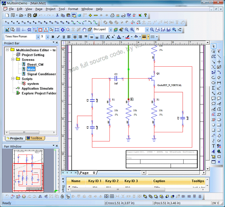
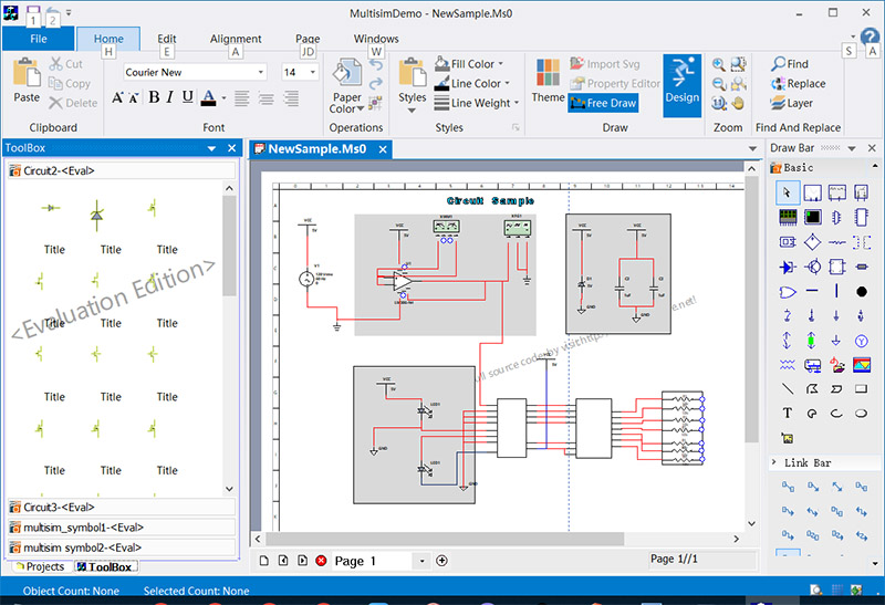
(Note: New V2025 is released, download and try it freely).
UCanCode Circuit Control:
This control is the control package of UcanCode's dedicated Circuit diagram
design tool. It provides professional circuit diagram design tools, including a
large number of components, various advanced connection lines and operations. It
can be deployed in various C#, Java, Web, Delphi and other applications. To
provide professional circuit diagram drawing function, as shown below:
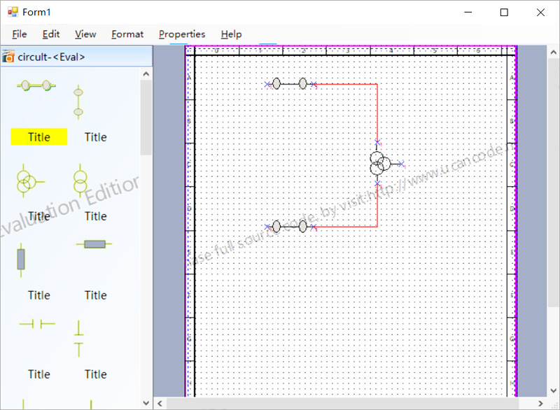
(For specific functions, please refer to the example in the UCC_Multisim folder)
Auto-align lines, auto-connect:
You only need to align the ports that need to be connected to a line (with
auxiliary lines), and the port-to-port connection will be performed
automatically.
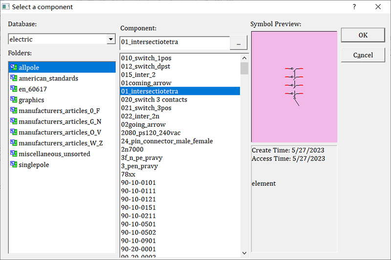
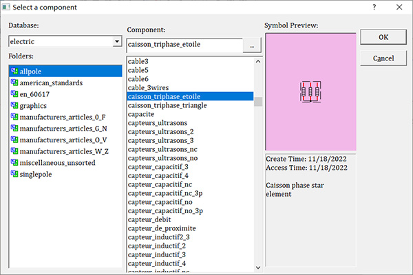
More than 9,000 various preset symbols:
As shown in the figure below, it can be automatically drawn by clicking the
mouse.
Features:
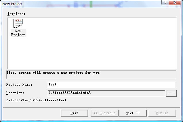
1. New project:
Create new project with the
following wizard:
2. Open project & Close
Project file.
3. Recent project files menu
items.
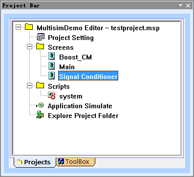
4. Project tree controlbar.
5. Add new circuit
drawing file into project, as below:
6. Add new script file into
project.
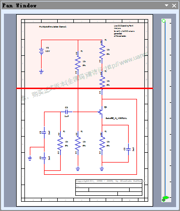
7. High - bird window, as
below:
8. Canvas border and margin, as
below:
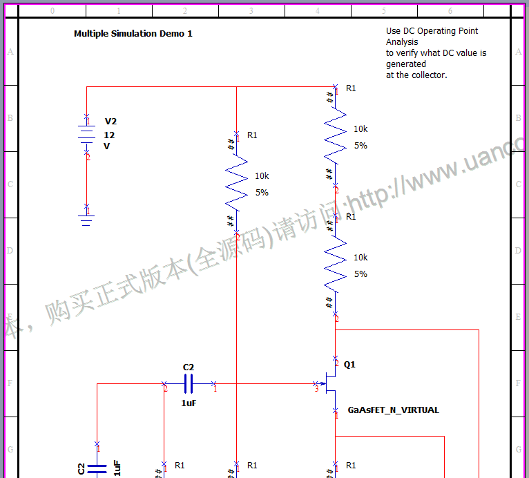
9. Title block support, as below:
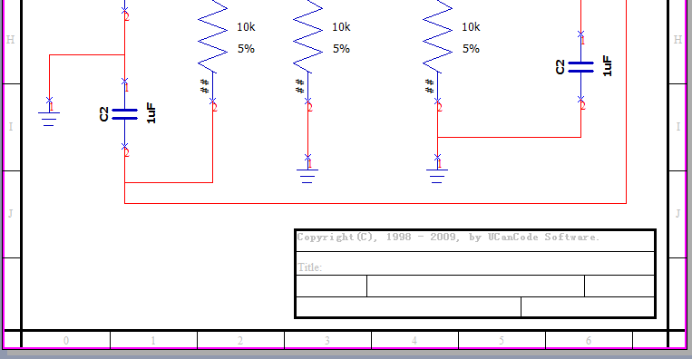
10. Moving and editing the
label of symbol shape.
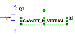
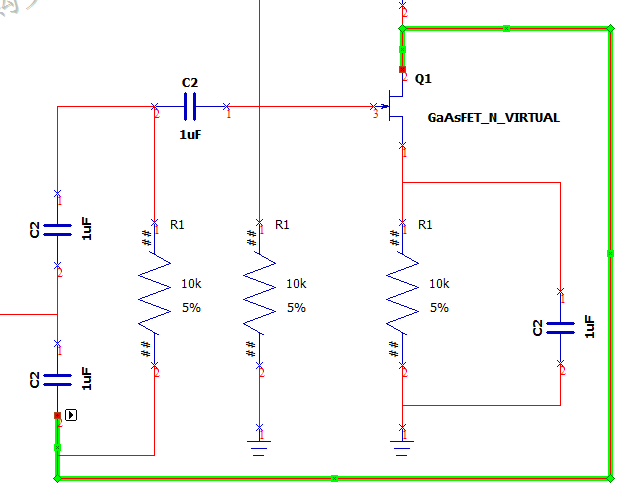
11. Connect between two
ports, as below:
12. Net list
It supports generate excel style
net list with all the shapes on the canvas.
13. Zoom the canvas by move
the wheel button of mouse.
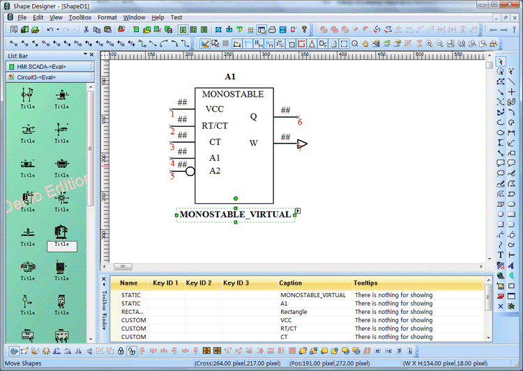
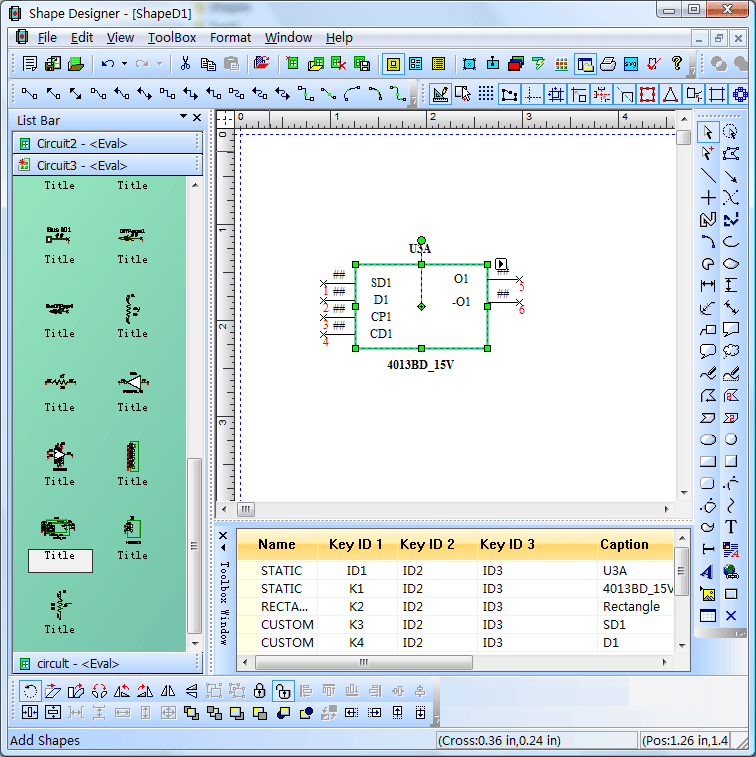
14. Symbol design:
With shapedesigner that shipped
with E-XD++ Suite, you can design any kind of circuit symbol quickly and easily,
as below:
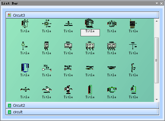
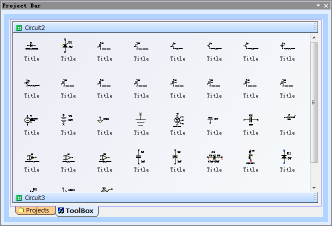
15. System basic symbols:
E-XD++ ships over 1000 kinds of
symbols, below are a list of them for circuit drawing:
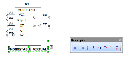
16. Circuit Symbols Pin Design:
E-XD++'s shapedesigner includes
professional circuit pin design, as below:
17. Other:
Since the full edition of E-XD++
Suite has over 500,000 lines full tested VC++ Source Codes, so there are over
1000 features that can be used for building your circuit application. All the
features of this circuit solution can be full customized.
"Diagramming
business logic when developing a custom application is a time-consuming,
tedious—and necessary—process. With E-XD++ Diagramming Source Code Kit,
you can spend more time focusing on the finer points of your customer's
business and less time worrying about making the business process
diagram look good. "
|


